Bicycle Brake Light Module
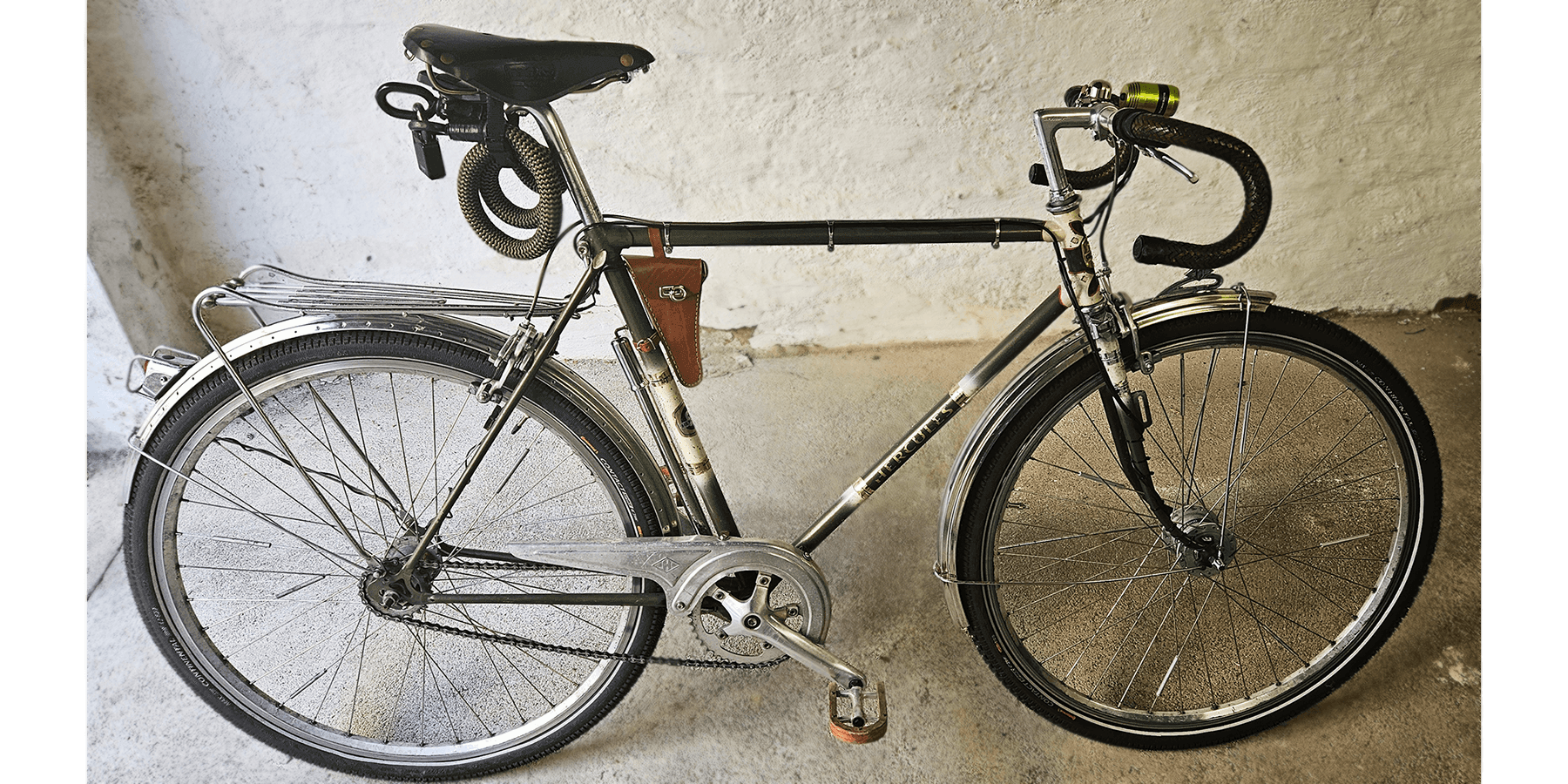
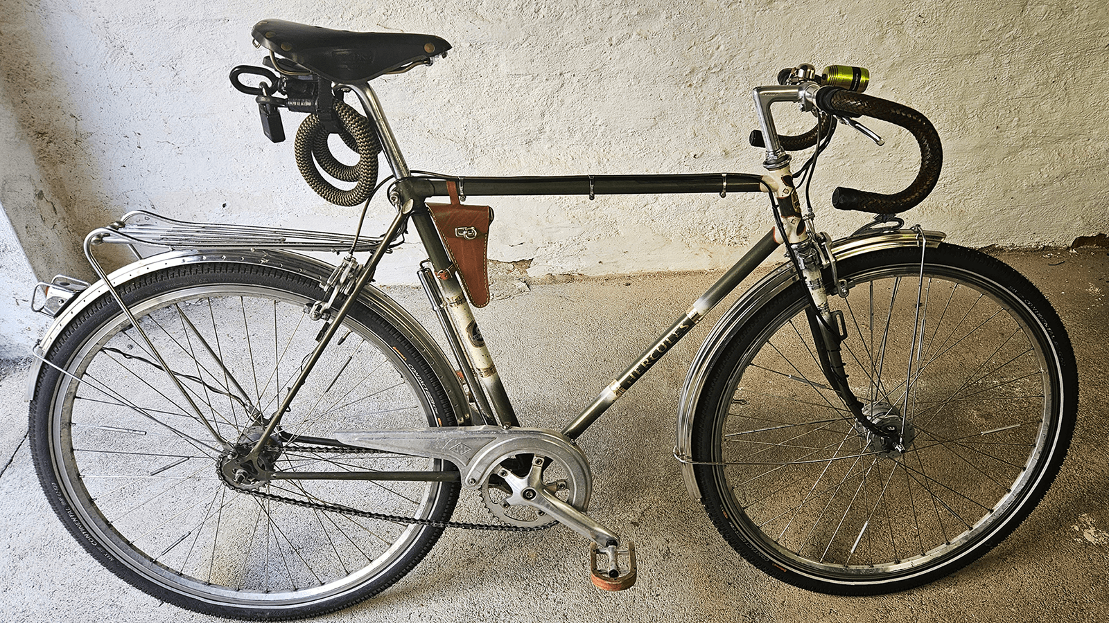
A friend of mine wanted to add a blinking brake light to his bicycle. Sounds simple enough... Just buy one of the existing solutions and you're done. But...
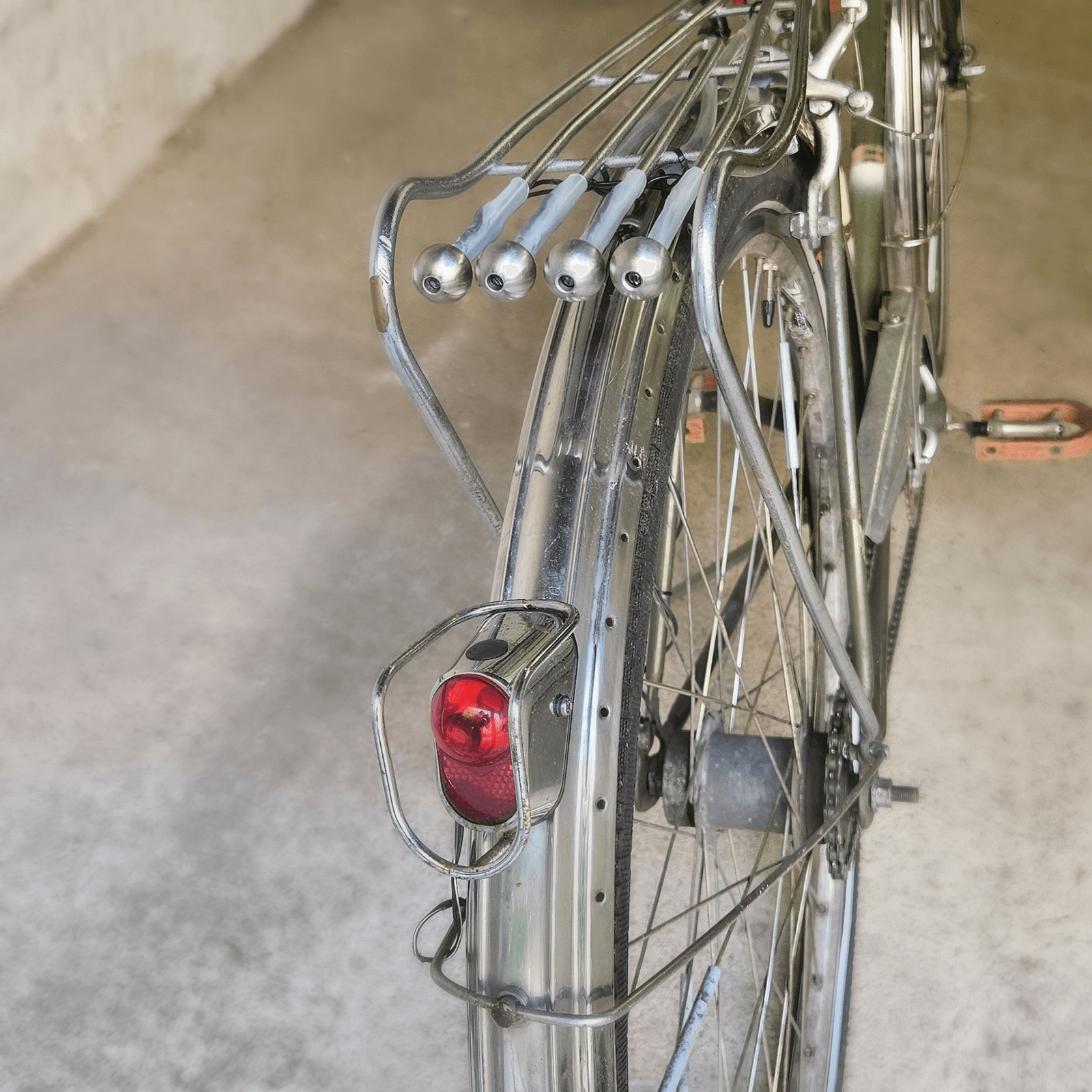
My friend had already designed a custom LED retainer for his bicycle's rear rack which looked pretty cool. And I then added the constraint that the "Brake Light Module" should be powered from the bicycle's dynamo (and not batteries). The bicycle is equipped with a Hub Dynamo so is the power is always on - as long as you're moving.
LED Assembly
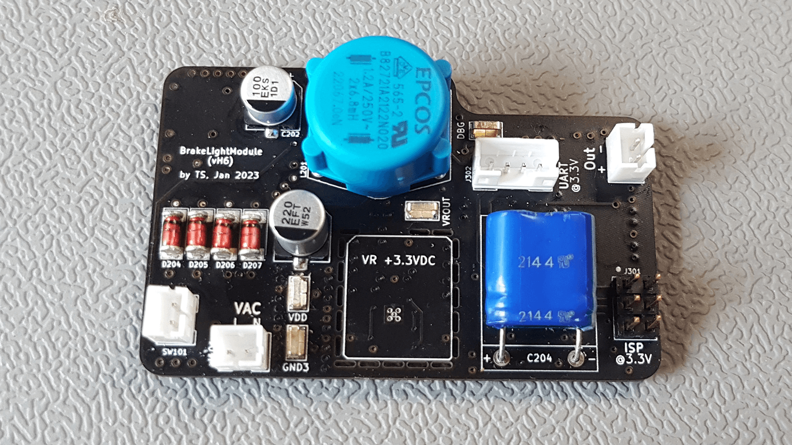
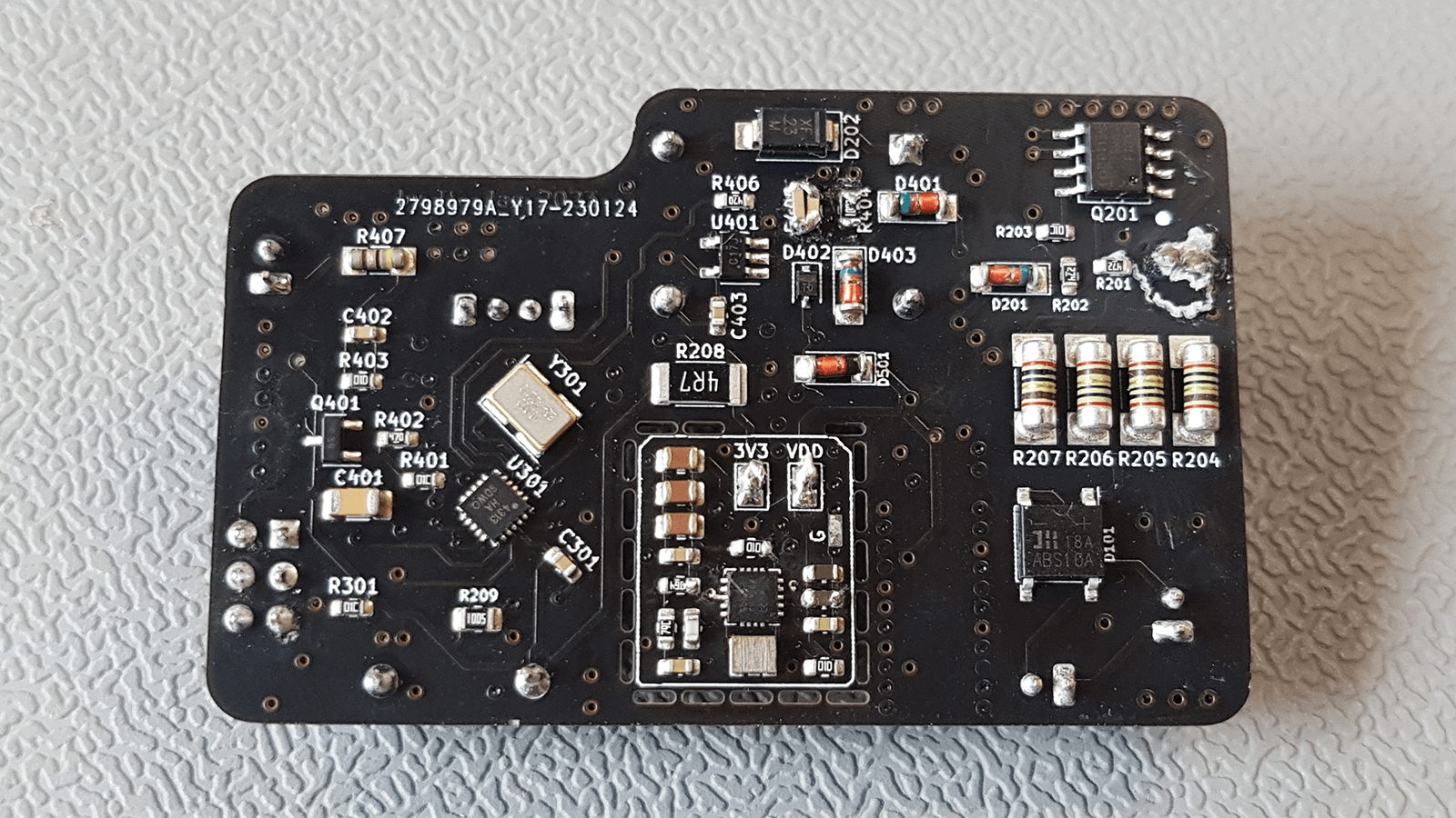
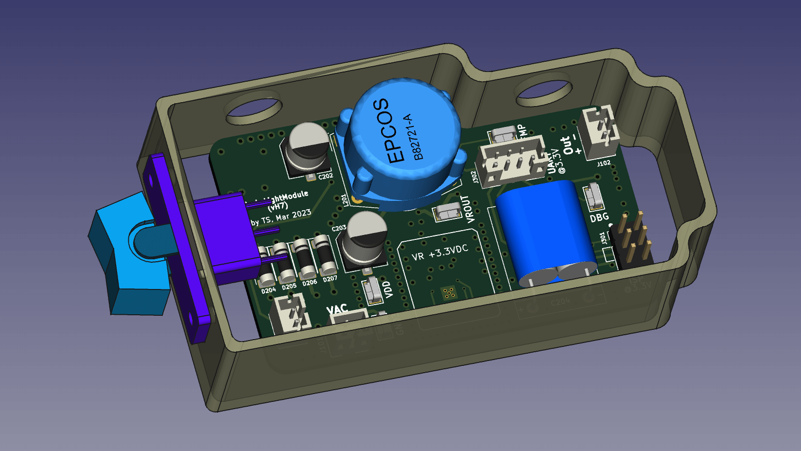
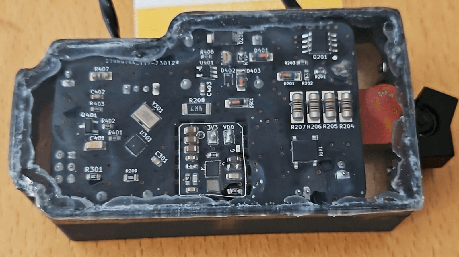
PCB Design
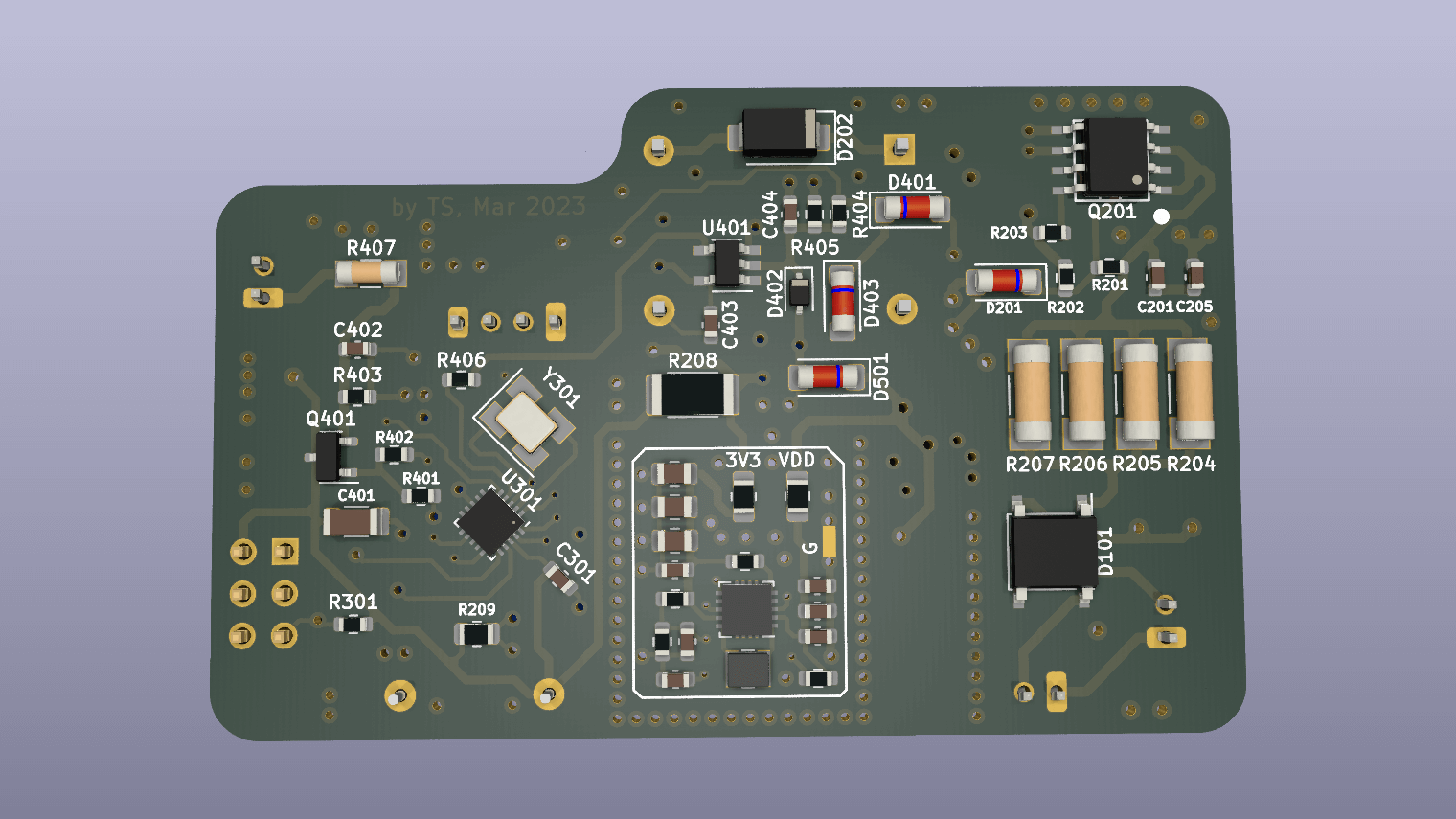
The PCB features are mainly the following:
- input voltage range is about from 3.5 up to 60 VAC RMS
- Overvoltage Protection (kicks in at about 19 VAC RMS)
- an external ON/OFF switch can be attached
- UART port for debugging purposes
- ISP port for programming the ATtiny4313 microcontroller
- external LEDs port for the actual LEDs (4x 5mm LEDs from Kingbright with about 4500 mcd and 20 mA)
- power consumption when running is about 34 mW and in when Sleep Mode about 26 mW
- Supercap for storing enough energy to keep the microcontroller running for over 15 min when the bicycle isn't moving and of course for powering the external LEDs
Testing the Overvoltage Protection was not feasible for me since I didn't want to build a test jig with an actual dynamo that was somehow powered by a rather powerful motor. But since any bicycle dynamo can only output a maximum power of about 4 W there should be no more than about 70 mA flowing when the dynamo is outputting 60 VAC. And my circuit should be able to handle that amount of power...
The nominal output of dynamos is generally something like 6 VAC RMS and 3 W with a 12 Ohms load.
Measurements
In order get the circuit and the firmware for the microcontroller right I had to do some measurements, of course.
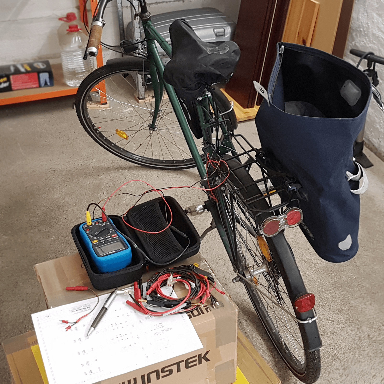
So first I measured the two kinds of bicycle dynamos out there: a Hub Dynamo (which is mounted inside the rim) and a Tire Dynamo (which is mounted on the side of the front tire). And I performed the measurements without a load and with different loads.
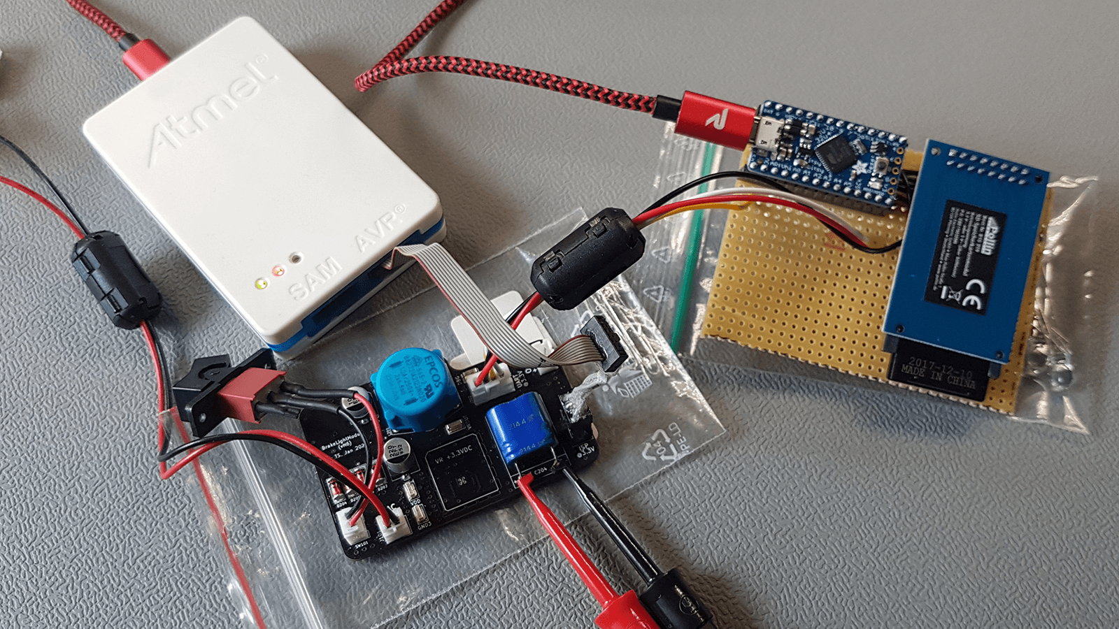
For taking the measurements while riding the bike I built a whole bunch of different kinds of adapter cables and put an EEVblog 121GW multimeter with an internal SD Card into a bag that is mounted to the bike.
And then later, when I already had a working prototype, I put together a simple UART to SD Card Logger with an ATmega32U:
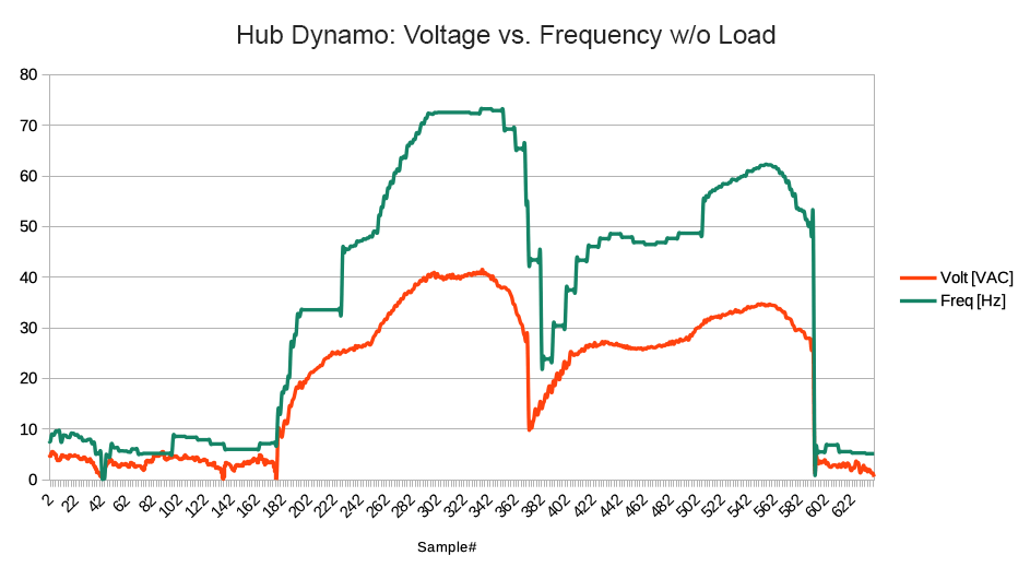
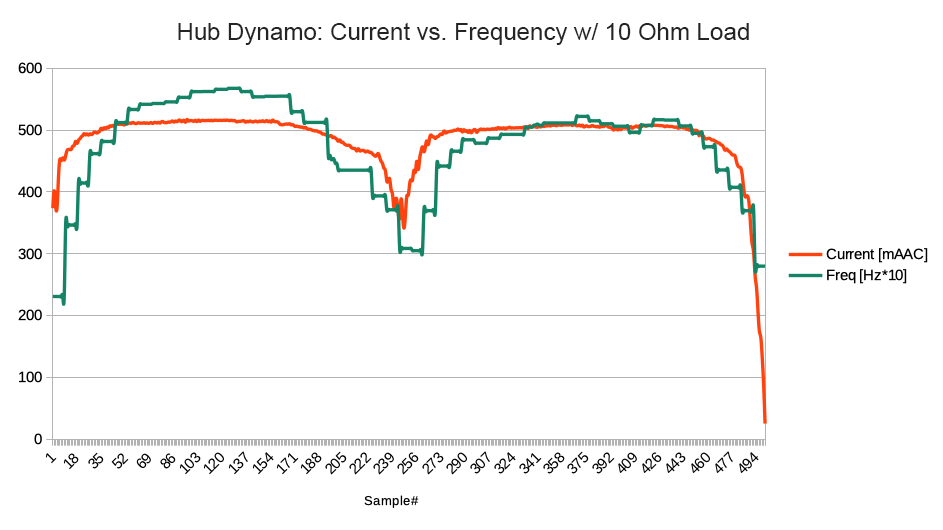
And the results looked like this:
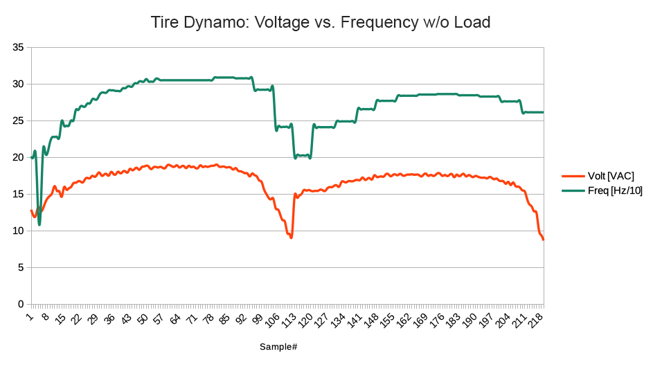
(Please note that the frequency in the right image has been scaled down by a factor of 10)
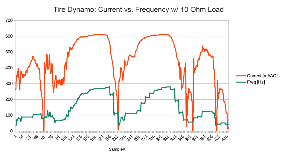
(Please note that the frequency in the left image has been scaled up by a factor of 10)
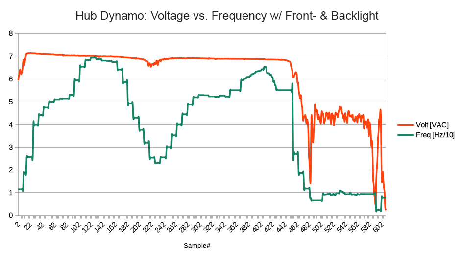
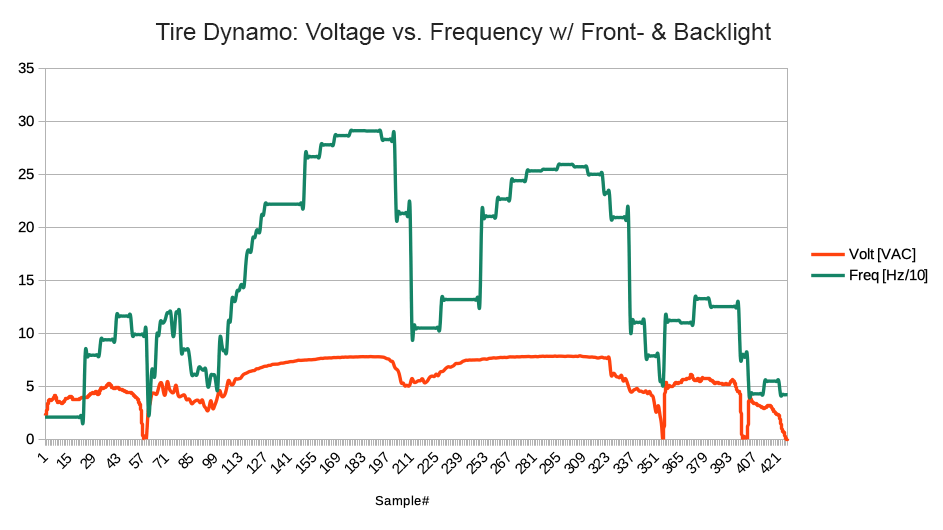
(Please note that the frequency in both images has been scaled down by a factor of 10)
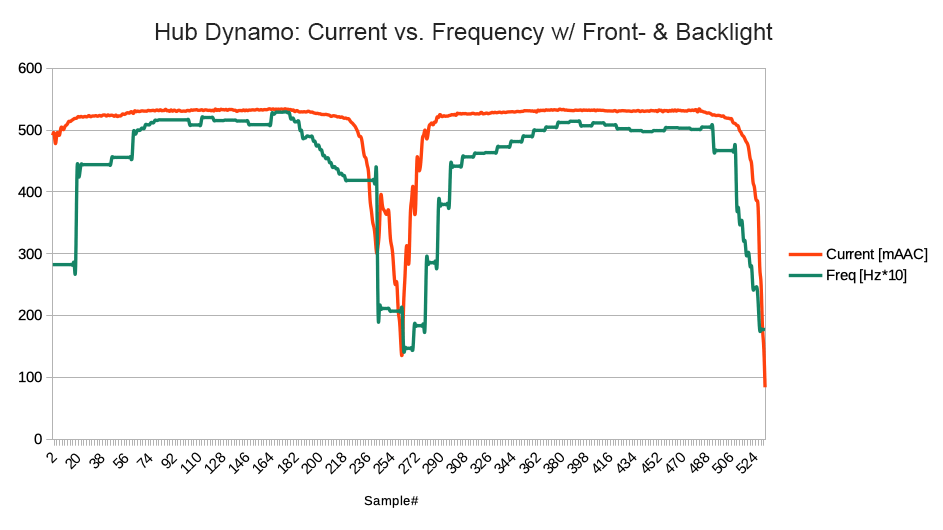
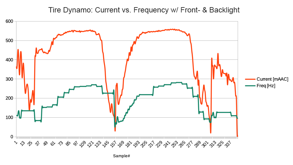
(Please note that the frequency in the left image has been scaled up by a factor of 10)
So in general the main difference between Hub and Tire Dynamos is the frequency of the AC voltage. And for the specific dynamos that I tested the Tire Dynamo could output a little bit more power.
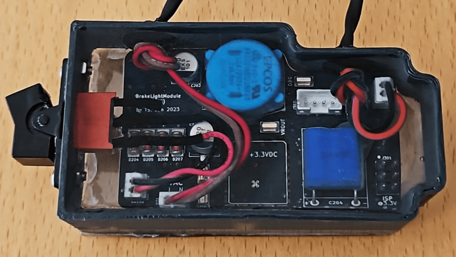
3D Printed Case
And of course no project is complete without a proper 3D printed case:
The round holes on the side got sealed with rubber gaskets.
The case has neither floor nor lid because I made a transparent floor out of acrylic glass and then poured epoxy into the case:
End Result
The Brake Light Module is hidden inside the leather tool bag underneath the saddle: