LED Ring Light with Rotary Encoder
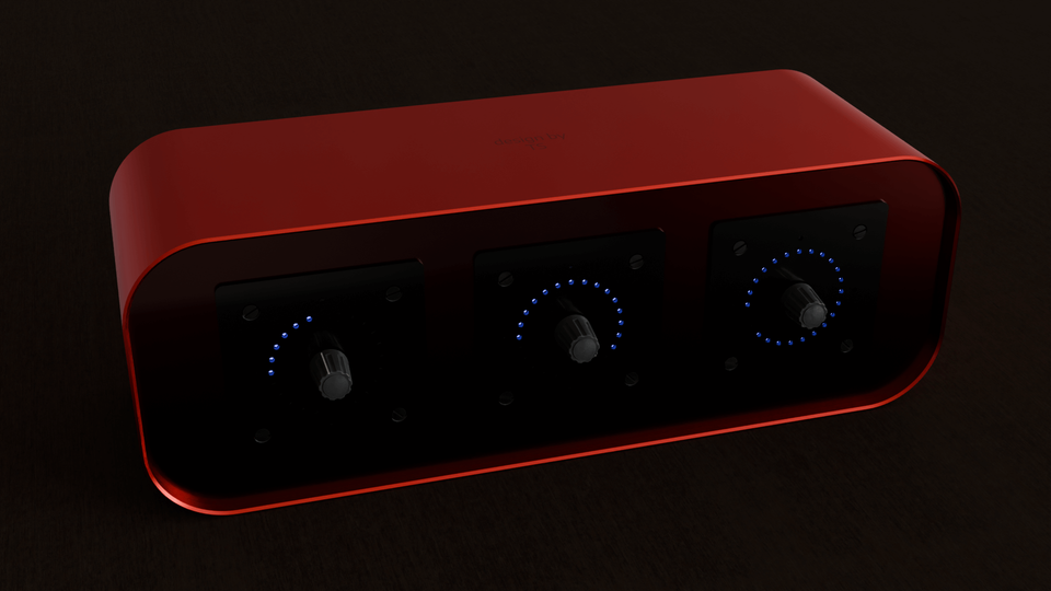
An LED ring light module with a rotary encoder, I2C interface, event trigger pin, four GPIO pins and daisy-chaining ability. It could be used to e.g. control and display the volume of audio channels and parameters.
This little module consists of three individual PCBs:
- one for flashing and debugging the firmware
- one for the microcontroller and rotary encoder
- and one for the LED driver IC and the LEDs
The PCB for flashing and debugging is only required for these tasks. Once the module has been flashed it can be detached. It has spring loaded "pogo pins" to make contact with the MCU board. But the footprint of the connector was designed such that regular 0.1" pin headers could also be used.
Communication with the host (e.g. a microcontroller or single board computer) is done via I2C. When the rotary encoder knob has been turned or pressed the event trigger pin will be pulled high for a short period of time to notify the host that a new event has occurred that needs handling.
The RP2040 microcontroller communicates with the LED driver IC via a separate I2C channel.
Each module's I2C address can be set with a DIP switch or in firmware. Since the modules can be daisy chained, it is possible to connect up to seven modules to a host with a single connector (labeled "PWR+I2C"). If the I2C address is set in the firmware one could even connect up to some 128 modules to a host.
Since every module requires up to ~500 mA @ 3.3 V (when all LEDs are lit at full brightness) the modules also have a connector for external power. But if only one module is connected to the host the host connection alone might be able to provide enough current.
PCBs
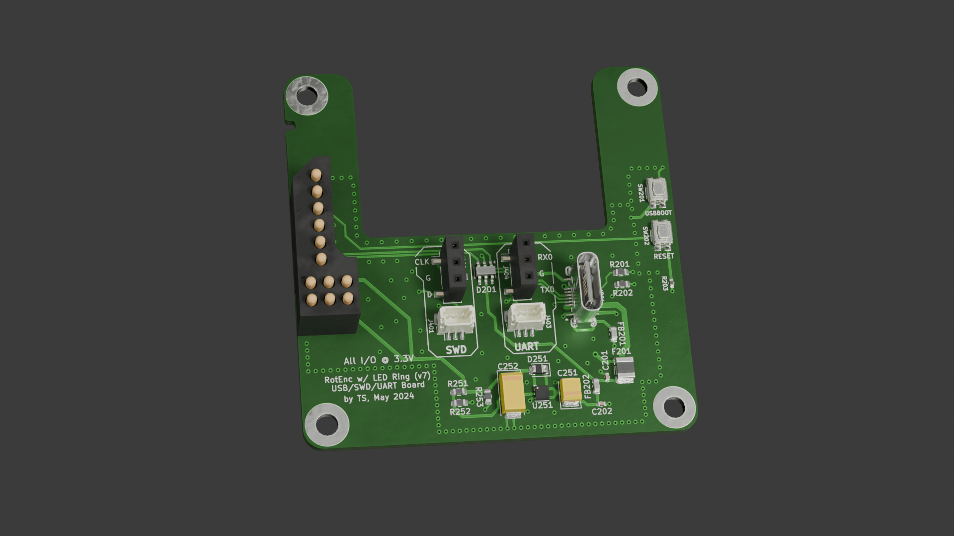
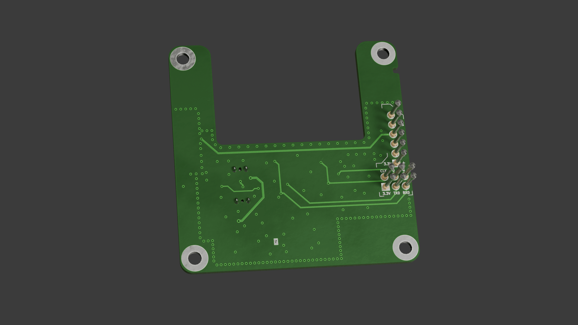
PCB for flashing and debugging
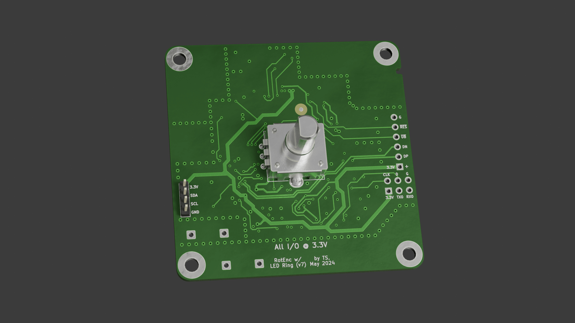
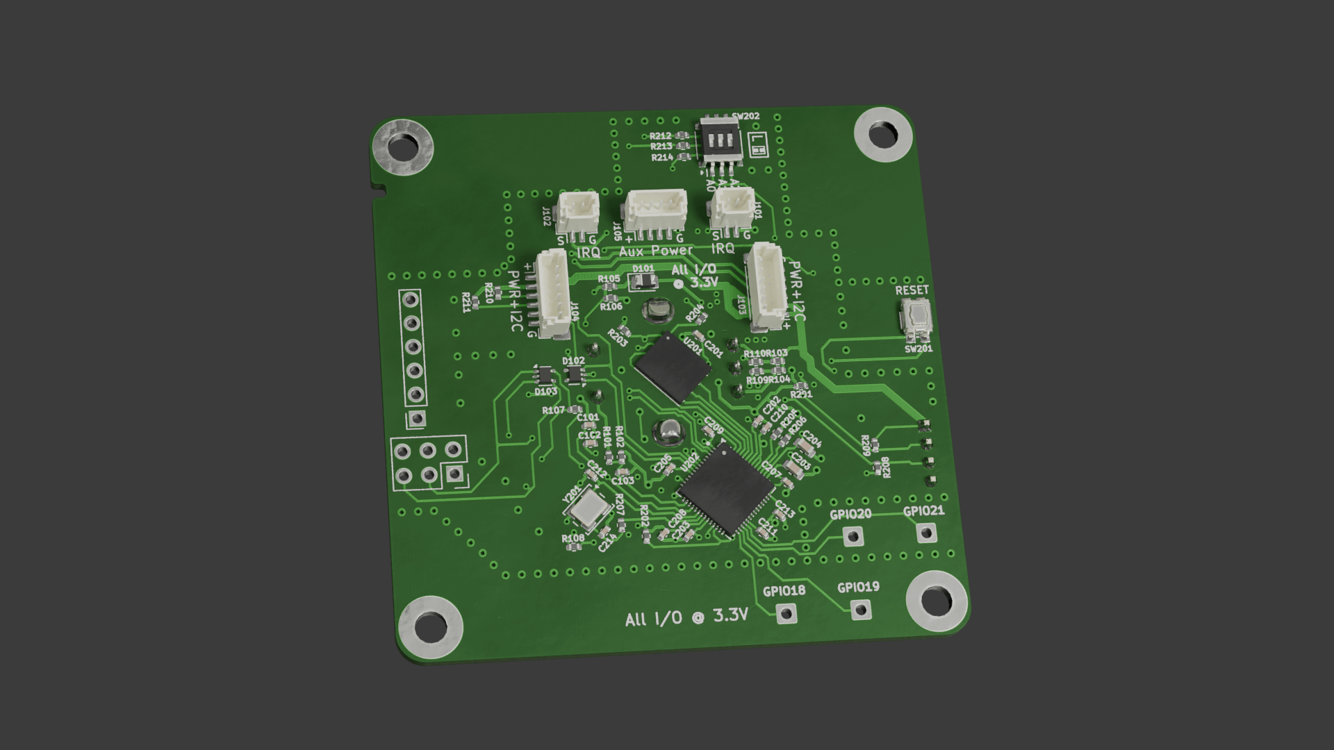
PCB for the microcontroller and rotary encoder
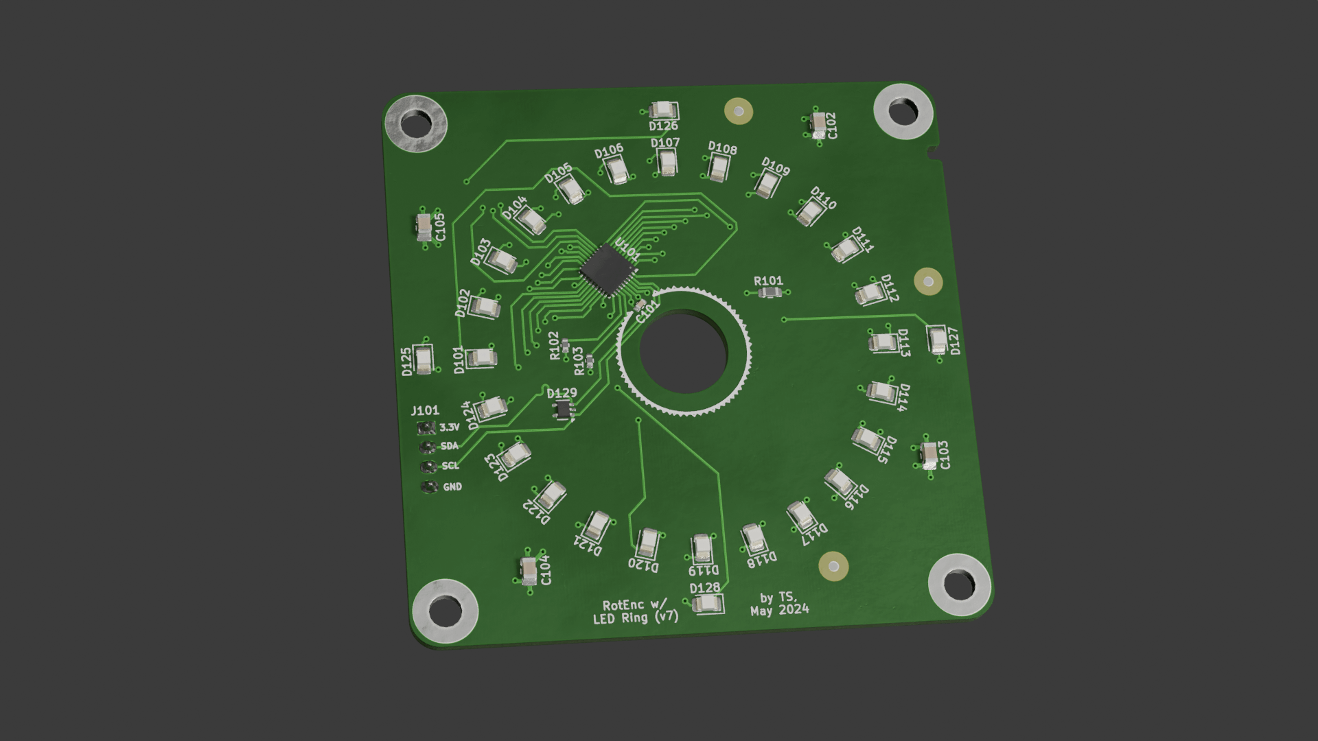
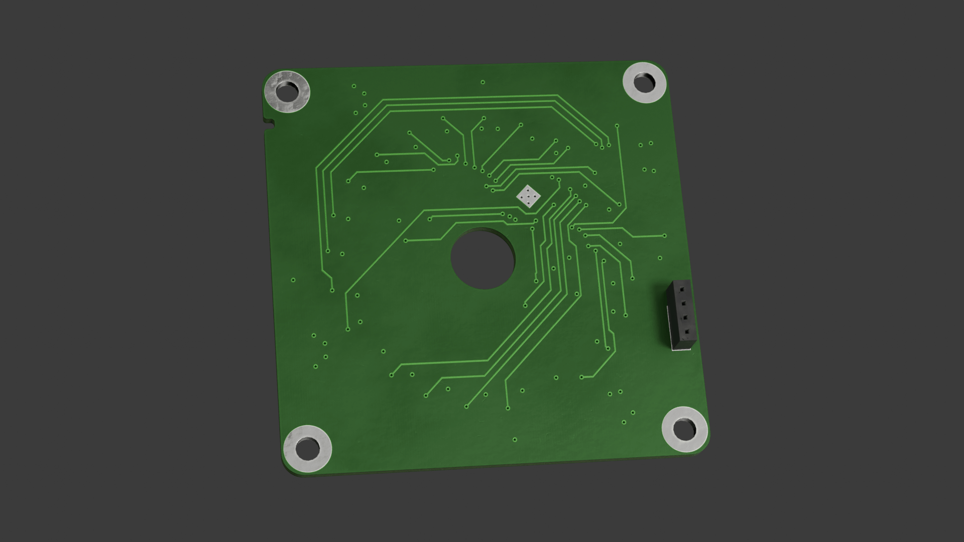
PCB for the LED driver IC and the LEDs
PCB Assembly
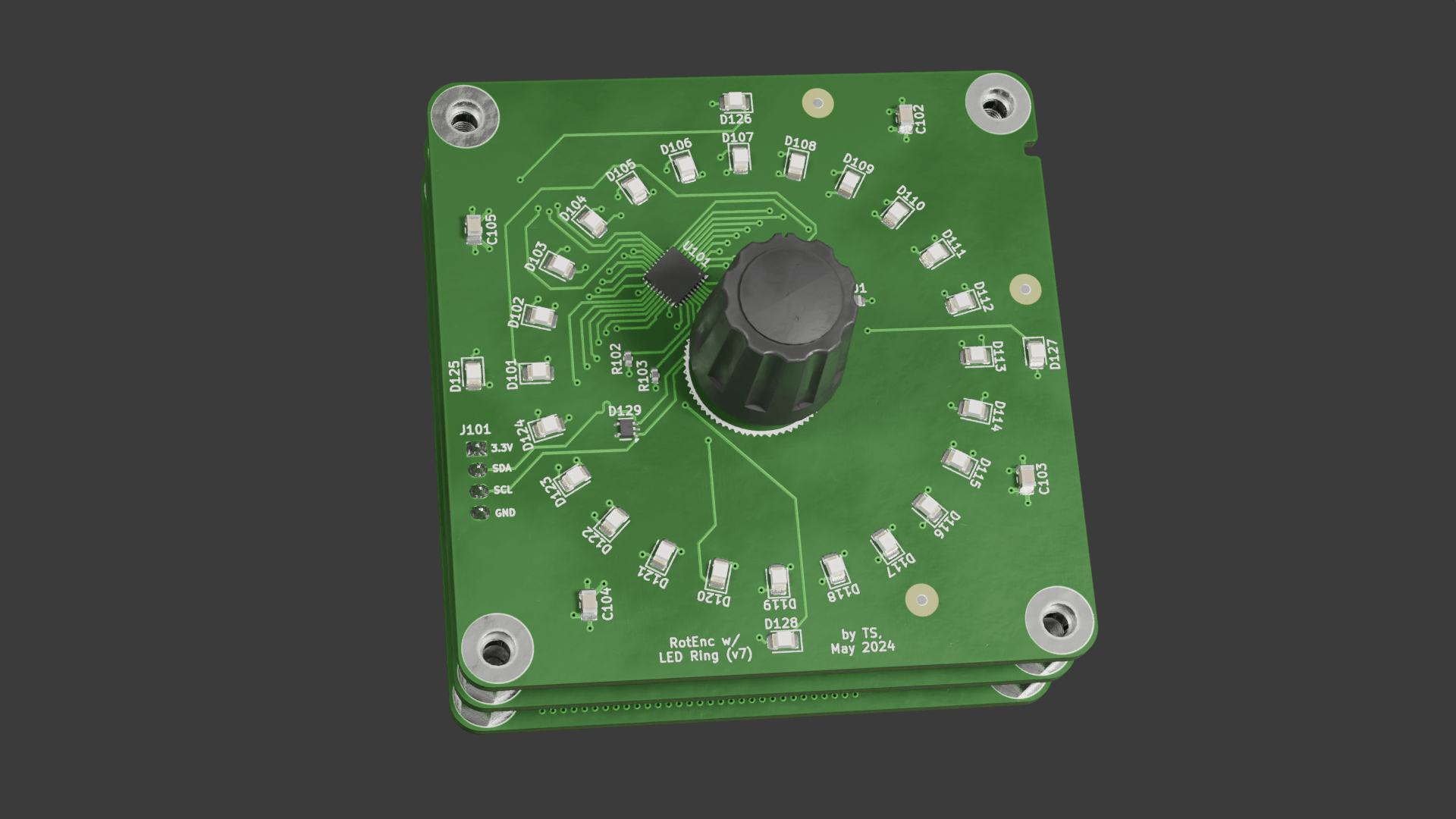
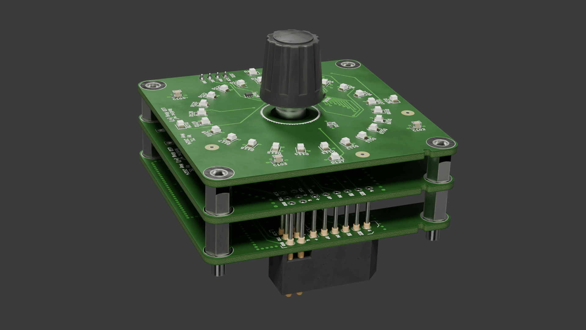
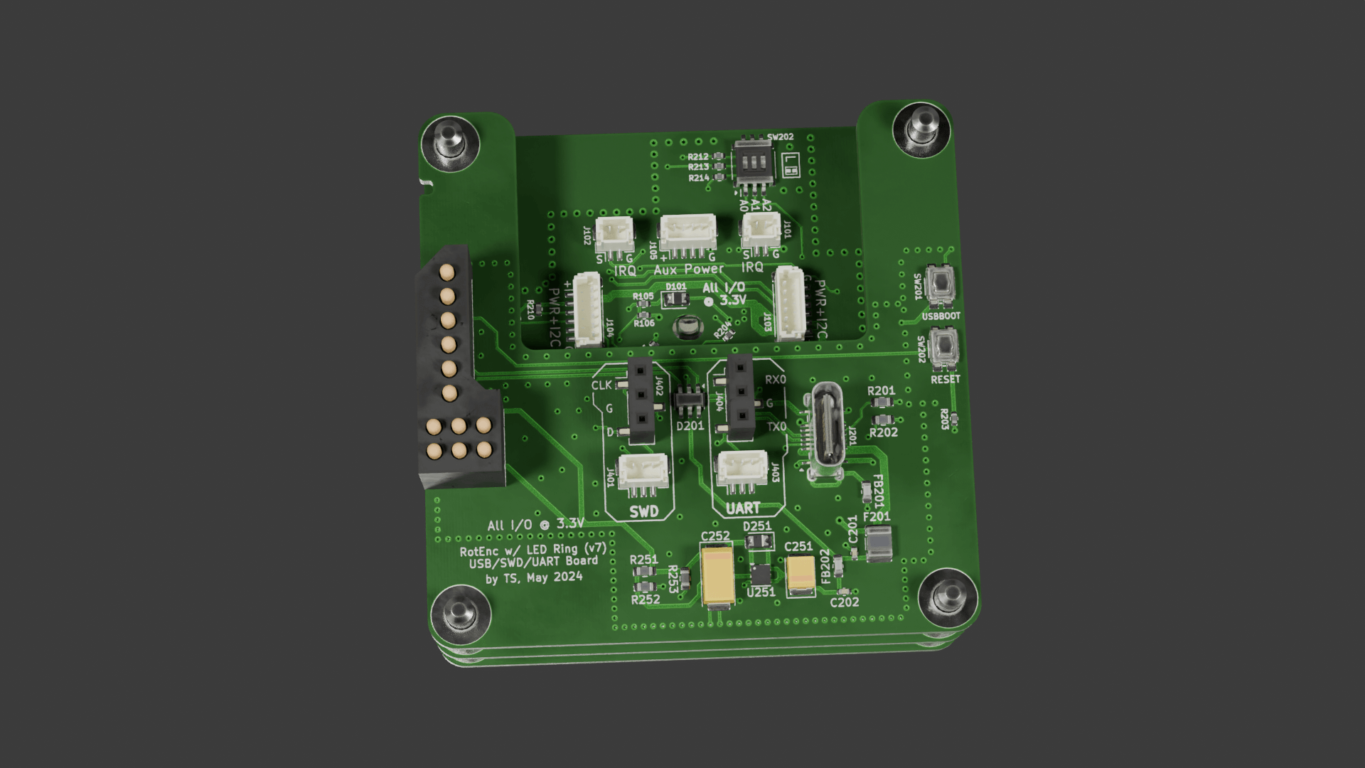
Views of all three PCBs assembled
Here's the previous version of the module (which had smaller dimensions) with all LEDs shining bright (green/yellow variant):
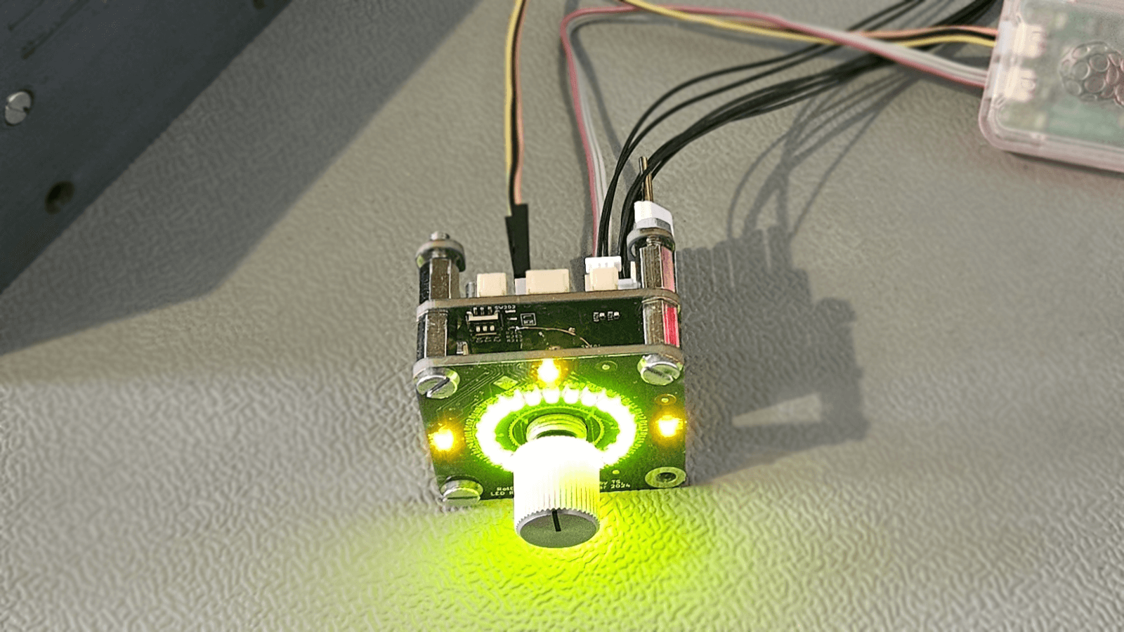
Green/yellow variant